
IBT’s fluid power team is often asked what information is needed to replace a hydraulic cylinder. In this article, we will address that exact concern, walk you through measuring the size of your hydraulic cylinder, and provide the information needed to replace your cylinder.
Hydraulic Cylinder Identification
Before we get too deep into measuring the cylinder’s size, we need to discuss the type of hydraulic cylinder that you are measuring. There are many types of hydraulic cylinders that you could be measuring.
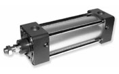
Standard cylinders are Tie Rod, Mill Duty, and Welded, as pictured below:
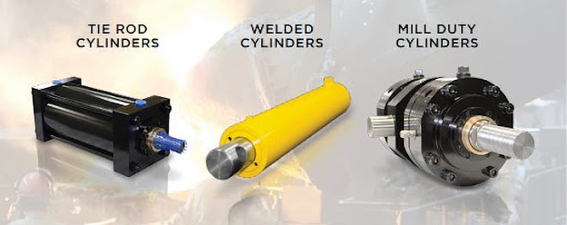
Tie Rod, Mill Duty, and Welded are all piston-rod cylinders. They have a piston inside and a rod that extends and retracts through the end of the cylinder. These cylinders can be single or double-acting.
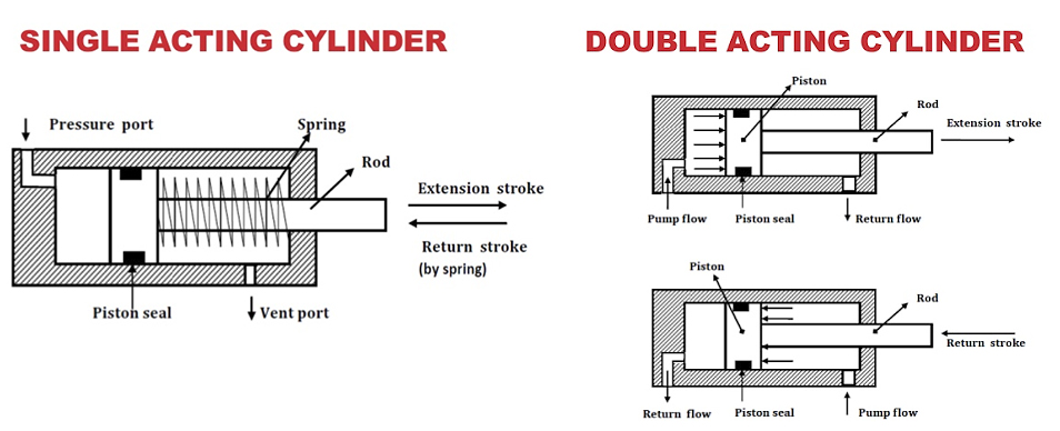
A single-acting hydraulic cylinder includes one port where the hydraulic fluid enters and forces the plunger out in one direction. Force must be applied for the cylinder to retract. This force can come in the form of an internal spring or an external force.
A double-acting cylinder consists of two ports: one for the hydraulic fluid to enter and extend the plunger, and another port for retracting the cylinder. Unlike single-acting, a double-acting cylinder uses hydraulic fluid pressure to retract.
To identify a single vs. double-acting cylinder, there is one common external feature to look for. A single-acting cylinder has a single hydraulic port and hose attached, whereas a double-acting contains two ports and has two hydraulic hoses connected to it.
Another feature to look for is a single rod vs. a double rod. A single-rod cylinder has one rod that extends and retracts out of one end of the cylinder. A double-rod simply has another rod that extends and retracts out of the other end of the cylinder, where both rods are connected to the piston.
The illustrations below show single-rod type cylinders, as they are the most common in industrial applications:
12 Steps for Measuring a Hydraulic Cylinder
Now that we have covered some of the different types of hydraulic cylinders, let’s get down to measuring the cylinder.
First, gather the proper tools and safety equipment required to quickly and safely record the measurements of your cylinder. Safety Equipment should include both eye protection and steel-toe footwear. Tools should include the following:
- Tape measure
- Calipers
- Thread gages or a known fitting size to check port and rod extension threads
- Other shop tools
- Something to record your measurements, or a step-by-step form to register your measurements
Additionally, there are several features that will help define the hydraulic cylinder being replaced, such as:
- Nameplate Check
- Bore Diameter
- Rod Diameter
- Stroke/Rod Extension
- Rod End Style
- Mounting
- Hose Ports
- Ambient Environment
- Working Pressure
- Manufacturer Drawing Verification
Step 1: Check for Nameplate or Part Number Information
The easiest way to find a replacement cylinder is to find the nameplate information and the cylinder part number. Most manufacturers use “Smart” Part Numbers or have history of the Serial Number. IBT Fluid Power Specialists are also experts at deciphering nameplate information and can provide assistance during this step of the process if needed.
However, sometimes nameplate information or the cylinder part number may be unavailable or untraceable. In that case, forgo checking for this information and continue on to the next step in measuring and replacing an existing hydraulic cylinder.
Step 2: Measure the Piston diameter
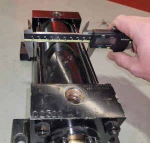 The piston diameter is the inside barrel diameter. Also known as the bore diameter, this diameter is the primary dimension of a hydraulic cylinder. If the cylinder is disassembled, measure either the inside diameter of the cylinder tubing or the actual piston diameter. If the cylinder is still assembled or installed, the bore diameter can be measured by using the outside diameter of the cylinder and subtracting the thickness of both tubing walls.
For example, if the outer barrel is two inches and you subtract 0.25 inches to account for each tubing wall, then the bore is equal to a 1.5 inch bore.
As a reference, below is a collection of the most common industry-standard tubing sizes:
| Piston Diameter (Bore) | Outside Barrel Diameter (Option 1) | Outside Barrel Diameter (Option 2) | Outside Barrel Diameter (Option 3) |
| 1.5” | 1.75” | 1.88” | 2” |
| 1.75” | 2.12” | 2.27” | N/A |
| 2” | 2.38” | 2.5” | N/A |
| 2.25” | 2.5” | 2.65” | N/A |
| 2.5” | 2.75” | 2.88” | 3” |
| 2.75” | 3.12” | N/A | N/A |
| 3” | 3.38” | 3.5” | N/A |
| 3.25” | 3.88” | N/A | N/A |
| 3.5” | 3.88” | 4” | N/A |
| 4” | 4.5” | 4.62” | 4.75” |
| 4.25” | 4.62” | N/A | N/A |
| 4.5” | 5” | 5.5” | N/A |
| 5” | 5.5” | 5.62” | 5.75” |
| 5.5” | 6.12” | N/A | N/A |
| 6” | 6.64” | 6.75” | 7″ |
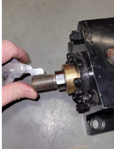
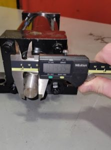
Step 3: Measure the Rod Diameter
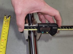
The next step is to measure the hydraulic cylinder rod diameter. The rod is one of the most critical parts of a cylinder because it transfers all necessary force during operation. Because of this, proper measurement of the rod diameter is crucial, as it helps prevent future rod bending.
The rod itself is made of either chrome-plated steel or stainless steel and moves in and out of the cylinder. Using a micrometer or caliper, measure the thickness, as this will reveal the rod’s diameter.
Step 4: Measure the Stroke
When measuring the hydraulic cylinder stroke, the goal is to find the distance that a cylinder travels. More technically, the stroke equals the extended length minus the retracted length of the rod.
If your equipment is down or non-functioning, the cylinder must be uninstalled, and then extended and retracted manually for precise measurement. If you are doing this on a cylinder that is still installed and functional, always use the manufacturer and your company’s lock-out tag-out procedures before reaching into the machine to measure the cylinder.
You may have to apply hydraulic pressure to the cylinder to extend the rod fully. Use necessary precautions when doing so, since atomized spray or mist of oil droplets may extend as far as 40 feet. The flammable oil spray can be ignited readily by hot surfaces and create a flash fire.
The more accurate the measurement, the better. If the cylinder stroke measurement is inaccurate, the replacement cylinder cannot be installed or operated correctly.
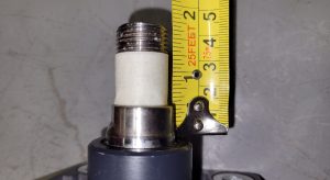
Step 5: Measure the Retracted Length of the Cylinder Rod
The retracted length is the distance between a fixed location on the cylinder and the marked location on the cylinder rod while it’s in the fully retracted position. In the image shown, we used masking tape to mark the cylinder rod and measured 1.25 inches from the rod wiper to where the tape ends.
Step 6: Measure the Extended Length of the Cylinder Rod
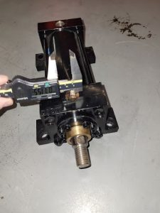
The extended length measurement is similar to the retracted length, but this time, we will measure the distance when the rod is fully extended.
First, extend the rod to its maximum extended position. Again, use a tape measure to find the distance between the same fixed point on the cylinder and the marked point on the rod. In the image shown we measured 13.25 inches from the rod wiper to the end of the masking tape.
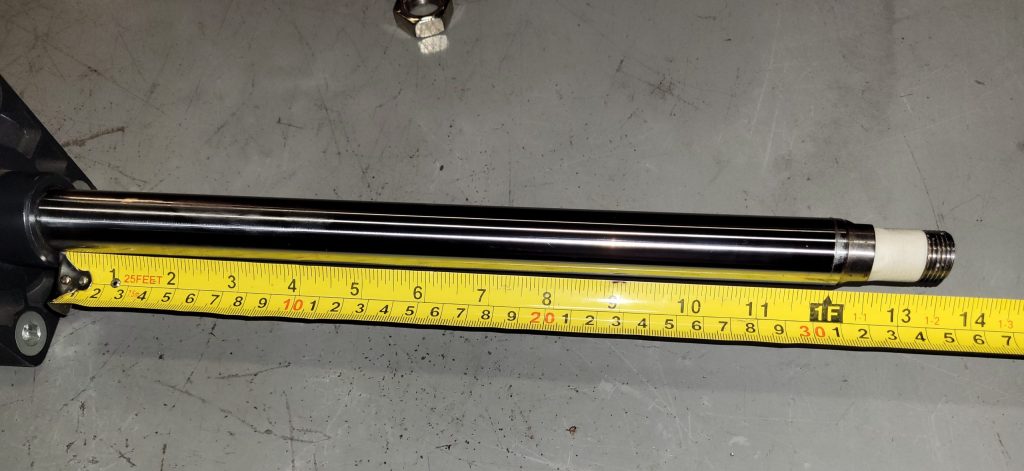
For this particular cylinder, the stroke is 12 inches.
13.25 in (Extended Length) – 1.25 in (Retracted Length) = 12.00 in
Step 7: Determining Rod End Style
There are many rod-end thread styles. However, the most common are standardized by the National Fluid Power Association (NFPA). These are Standard Male, Standard Female, and Intermediate Male.
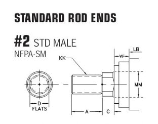
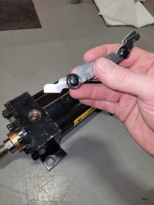
When measuring the rod end, you will need to check the threads using a standard thread gauge and calipers. Other dimensions should be measured and noted, as well. These can be compared to manufacturers’ NFPA published standard sizes for accuracy.
Step 8: Determine Mounting Style
There are several methods for mounting a hydraulic cylinder. The original equipment manufacturers (OEM) vary how their cylinders are mounted. The standard mounting for industrial cylinders would be the Flange Mount, and the standard mounting for mobile equipment would be the Pivot Mount.
5 Most Common Hydraulic Cylinder Mounting Styles:
- Flange Mounts: Head or Cap Rectangular or Square Flange; Head or Cap Rectangular Integral Flange; Head or Cap Square Integral Flange
- Side Lug Mounts: Side Tapped; Side End Lug; Centerline Lug; Side Angle Mount
- Pivot Mounts: Fixed Clevis; Detachable Clevis; Fixed Eye; Detachable Eye; Spherical Eye
- Trunnion Mounts: Head Clevis Trunnion; Cap Trunnion; Intermediate Fixed Trunnion
- Tie Rod Mounts: Both End Extended Tie-Rods; Head Extended Tie-Rods; Cap Extended Tie-Rods
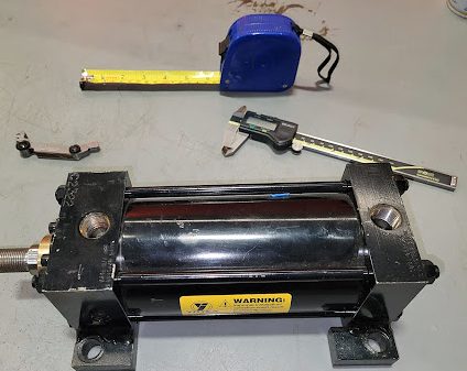
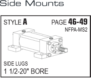
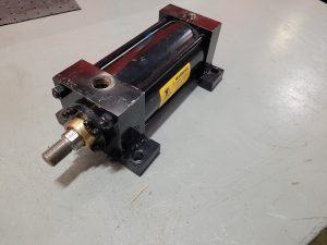
As an example, the cylinder shown below would be a Side Mount-Side Lug (MS2) mounting style:
When replacing a cylinder, you will need to confirm that the replacement is the same and that the outer dimensions will work with your frame allowances for correct fitment.
The NFPA publishes standard mounting types, allowing manufacturers to use this visual matrix to help you identify the mounting style on NFPA Tie Rod Cylinders. For further help, download the NFPA Tie Rod Cylinder Mounting Types matrix.
Step 9: Identify Size and Location of Cylinder Hose Ports
Next, evaluate your existing hydraulic hose ports. The hose port is where the hydraulic lines connect to the cylinder. Without the hoses attached, your cylinder will not work. Each hose has two crimped ends with either male or female ends. The most common design features female ports on the cylinder and requires male hose crimps to be connected.
Every hydraulic port has two other important designations, including thread type and size. For reference:
Hose Sizes:
- ¼-inch
- ⅜-inch
- ½-inch
- ¾-inch
Thread Types:
- SAE (O-Ring Boss)
- NPT (National Pipe Thread)
- JIC (Joint Industry Council)
If the cylinder that you have chosen is different from the thread of the hose, then an adapter can be utilized to make the correct connection. The port sizes shown above are a few of the options available for cylinders. Additionally, the OEM can have custom ports designed into the cylinder. Remember: always check the size closely.
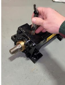
To measure the hydraulic cylinder ports, use a thread gauge and caliper to determine the thread pitch and size. You can also use known fitting to determine thread type and size as an alternative method. Using a thread gauge to determine pitch is illustrated below.
Port location is also essential. Ports can be located on the top, sides, or bottom of the cylinder.
Step 10: Keep Environment in Mind
External factors such as working temperature, dust contact, and corrosive materials should always be noted when measuring a hydraulic cylinder. Knowing these factors is vital for selecting the correct materials, wipers, and seals for your hydraulic cylinder.
Step 11: Determine the Working Pressure
The hydraulic cylinder’s working pressure can be determined by your application and the hydraulic system the cylinder operates in. Hydraulic pumps produce a maximum pressure and can be measured at the cylinder ports or found in manufacturer manuals. Typical industrial hydraulic cylinders come in Medium Duty (up to 1500 PSI) and Heavy Duty (up to 3000 PSI).
In some cases, even higher pressure duties are required, with some as high as 10,000 PSI or more, for excavators, hydraulic presses, hydraulic jacks, and other heavy-duty equipment.
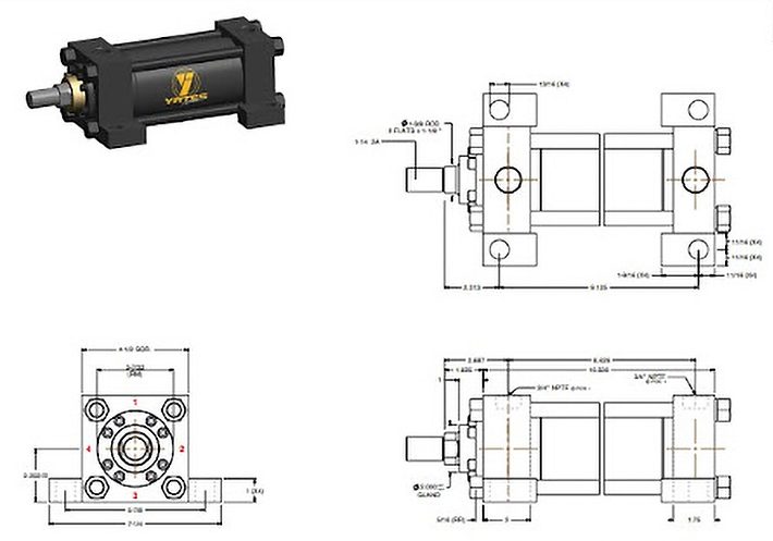
Step 12: Compare to Manufacturer Drawing
The final step in the hydraulic cylinder measurement process is to compare your measurements to a manufacturer’s drawing before you order. Cylinder drawings can be configured using our manufacturer’s configuration tools, and a two-dimensional or three-dimensional drawing can be provided in most cases.
IBT and our manufacturers require a signature verifying the dimensions of a cylinder on all orders. This ensures that we get it right the first time and provides a good record for future orders.
Here is an example courtesy of Yates Industries’ configuration tool:
Learn More from IBT’S Fluid Power Solution Experts
This step-by-step measurement process can help you determine the size of your hydraulic cylinder, ensuring that the replacement part will be the correct size and fit to keep you up and running.
With our years of experience in providing fluid power options, you can rely on IBT’s Hydraulic Division for the best solution to your problems. Contact Brent Hanson, the IBT Fluid Power Director of Business Development, at (913) 261-2125 to learn more.
Shop Our Online Catalog of Hydraulics & Accessories
Check out ShopIBT.com to find the hydraulic solution for your needs!